Smart Outlet
Introduction
Group Members: Joshua Haas, Graham Umaluf, Andrew Furlong, Zachary Kooker Class: Digital II (Professor Muhlbaier) Time: Junior Spring (2014) This project controls an AC power outlet using a website. This was implemented using a BeagleBone Black, a PIC32 microcontroller, and a TRIAC. Two outlets can be turned on or off and the power drawn from them can be measured from the website.
Motivation
Home automation is an up and coming market that appeals to a wide audience. What isn’t so appealing, however, is the generally large price tag. Therefore, we plan to develop a “Smart Outlet” that emulates some of this functionality using the relatively cheap development platforms of the BeagleBone Black and the Microchip PIC32 microcontroller. This combination should allow implementation of remote management, including current monitoring and switching.
BeagleBone Black
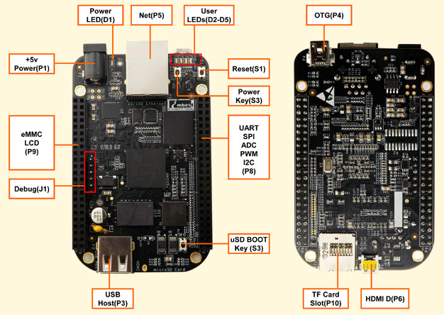
The BeagleBone Black (BBB) is a very small, $45 computer. It features a 1GHz ARM processor, numerous GPIO ports, and ethernet. It runs a distribution of Linux called Angstrom by default. In this project, The BeagleBone Black will be running a web server accessible by anyone over the internet. For a real implementation, this would obviously require some form of security, but that is outside the scope of this project. It also served as the hub for our smart outlets.

Implementation (BBB)

The user interface consists of a website hosted by the BeagleBone Black, namely BeaglePowerControl.php, which was implemented using the Lighttpd webserver. Clicking buttons on the website turns outlets on or off and can also read the power usage on each outlet. Clicking a button calls a PHP script embedded in the webpage, which invokes Fast CGI (Common Gateway Interface) to execute code in a bash shell. This in turn runs a python script on the BBB, namely UART.py. The command line parameters passed to the script vary based on what button was pressed on the webpage. It uses the PySerial package to communicate with the connected Smart Outlets over the Universal Asynchronous Receiver/Transmittter (UART) protocol. The BeagleBone Black has 5 UART ports (3 of which are user accessible). In this project, we only implemented control of 2 Smart Outlets due to required parts and time constraints, but each BBB could potentially connect to up to 3 over UART.

Microchip PIC32
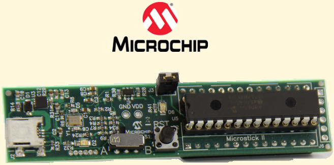
The Microchip PIC32MX250F128B is a 32-bit Microcontroller, which can easily be developed on using the Microchip Microstick II. It features a 50MHz core clock, 10-bit ADC, several analog and digital I/O ports, built-in UART module, and JTAG programming. In this project, two PIC32s will communicate with the BeagleBone Black (BBB) via UART. Thus, the BBB serves for user interface and as the master, with the PIC32s as the slaves. The PIC32s are also powered from the BBB, since in this application they draw less than 20mA, which eliminates the need for a separate DC power supply. Each PIC32 is using the following: UART TX and RX pins, 2 digital output pins, and one analog input pin. The UART pins are connected to the BBB for communication. The 2 digital output pins are used to control the TRIAC. Pin 16 (RB7) is set to always 3.3V and is connected to pin 1 on the optoisolator. Pin 17 (RB8) is set to 3.3V to turn the TRIAC off, and 0V to turn the TRIAC on. The analog input pin is connected to the current transformer to read the power usage on the outlets.

TRIAC
A TRIAC (from TRIode for Alternating Current) is a switching device for AC sources. The TRIAC used in this project is an ST Microelectronics BTA25. It has three terminals called Main Terminal 1 (MT1), Main Terminal 2 (MT2), and the Gate. When there is a voltage difference between MT1 and the Gate, causing current to flow into or out of the gate (minimum 50mA for this device) the TRIAC allows current to flow from MT1 to MT2, and from MT2 to MT1. There is also a phenomenon known as the holding current, whereby a constant current in either direction across the main terminals will keep the TRIAC conducting as long as the current remains above the threshhold (for this device 500mA). However, when used for AC power this isn't a concern, since there will be no current 120 times a second due to the sinusoial voltage of AC. It should also be noted that inductive loads can maintain a voltage across the terminals through the zero current region, thus keeping the TRIAC on even when there is no triggering current on the gate. This is generally fixed using a snubber circuit to prevent sudden voltage spikes (usually a simple RC circuit in parallel with the TRIAC), although our device is "Snubberless", having such functionality already built-in. This TRIAC can handle up to 25A RMS current, 260A peak current (for 16.7 ms), and 600V across any of its terminals. Also of note is the metal backing, which is insulated. Finally, TRIACs have a leakage current (i.e. some current flows even when the device is off), but this is only micro-amps and is thus negligible.
Opto-Isolator
It is never a good idea to directly interface a microcontroller that works on the order of 3.3V and mA directly with AC mains devices that work on the order of 120V and 10A. Due to the huge difference (and DC vs. AC) an optoisolator is a good idea. We chose the Fairchild Semiconductor MOC3063 to fulfill this role. On the input side of the device, a microcontroller controls and LED. When the current is flowing and the LED is emitting light, it activates a phototransistor on the output side. This device requires at least 5mA to turn on its LED, which has a voltage drop of about 1.15V at room temperature and 5mA. This would require a resistor of 430ohm, so 390ohm was chosen. Thus, applying a current to the input pins allows current to flow across the output pins. The input and the output are electrically isolated from each other, so even if a power surge or short happens on the mains side, it is virtually impossible for it to harm the microcontroller. In addition, our particular device features a zero-crossing detector. Basically, even if a current is applied to the LED and wants to turn on the transistor, the detector waits until the voltage across the output terminals is zero before letting current flow between the output pins. This prevents voltage spikes from inductive loads that would likely happen if the TRIAC were switched on at the peak of the voltage waveform, resulting in a huge di/dt and correspondingly hude dv/dt from the inductor. This behavior also limits potential RF noise caused by said spike.

The circuit used in this project was taken stright from the MOC3063 datasheet, and can be seen below. The only difference is that the snubber circuit (39ohm resistor and 0.01uF cap) were not included because our TRIAC was snubberless. Also, the circuit in the datasheet was actually designed for 240V, but will still work fine at the normal household 120V mains. When the MOC is off (no current from pin 1 to pin 2), the MT1 on the TRIAC is at the same voltage as the Gate, since no current is flowing through the 360ohm resistor on pin 4. When the MOC is on (current applied from pin 1 to pin 2) the AC mains produces a current through the resistor on pin 4, thus creating a voltage difference between the gate and MT1 on the TRIAC, and causing a current to flow into (or out of, either is fine) the gate, thus turning on the TRIAC. The 360ohm resistors do not experience significant power dissipation because the resistance through the TRIAC is much, much lower.
Current Transformer

Reading the current directly from AC mains is just as bad, if not worse, than interfacing the microcontroller with the TRIAC. In this case, a current transformer was chosen as an easy solution. It is basically a special kind of inductor with a clip. When clipped around one half of an AC power line (in our case the hot), the current through the wire creates a magnetic field that induces a current in the transformer. Thus the microcontroller will, once again, be isolate from direct contact with the AC mains. Our particular current transformer produces 15mA at its output for every 30A applied to its input. In order to read this from the PIC32, we need a voltage, and so a resistor was placed between the two terminals of the TRIAC. In addition, since the AC mains will cause an AC current in the transformer, we have to DC offset the voltage from across the resistor, since the PIC32 can only read from 0V to 3.3V. The voltage was offset by 1.65V using a coupling capacitor of (1uF) and a voltage divider to divide 3.3V in half (two 100kohm resistors). We then decided on a 10A maximum allowable current for the load on our SmartOutlet. Therefore the maximum possible current generated by the transformer would be 10A*(15mA/30A) = 5mA. In order to limit the generated voltage from 0V to 3.3V, we chose a maximum excursion of 1.5V, which would create anywhere from 1.65V-1.5V = 0.15V, to 1.65V+1.5V = 3.15V. Given a max of 5mA and +/- 1.5V, a 300ohm resistor was placed across the transformer. The circuit is shown below. Note that power (watts) was estimated as the RMS voltage (~116V AC) times the RMS current (read from the current transformer via PIC32). For highly inductive loads, this may not be entirely accurate, as the voltage and current waveforms would have to by multiplied in real time (i.e. current or voltage could be out of phase or not sinusoidal).
Implementation (PIC)
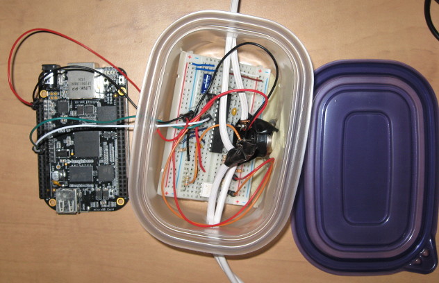
A normal extension cord was chosen to serve as the easy-to-build prototype for the SmartOutlet. For safety, all exposed connections to AC mains were places inside a plastic container to prevent potentially fatal electric shock. The extension cord was cut in half, and the two neutral wires were re-attached inside the box. The hot wires were soldered to MT1 and MT2 on the TRIAC, with the load (female end) of the extension cord attached to MT1. The PIC32 was placed on a breadboard along with the MOC3063 and all relevant resistors and capacitors. Using the 10-bit ADC on the PIC32, and based on the 1.5V excursion per 10A on the current transformer, we were able to calculate the resolution for reading the power usage. The 10-bit ADC can read values from 0 to 1023 corresponding from 0V to 3.3V. This gives a voltage resolution of 3.3/1024 = 3.223mV. This corresponds to currents through the 300ohm resistor of 10.74uA. And on the input of the current transformer of 10.74uA*(30A/15mA) = 21.48mA. Finally, with an RMS voltage for mains of 116V, this gives a power resolution of about 2.5W. So not incredibly precise, but probably good enough for the general home user.
Files
Conclusions
The SmartOutlet worked as expected, allowing us to turn a lamp on and off from a computer or smart phone. The power reading was relatively accurate as well, measuring 15W for the 13W bulb. Although that's an error of about 15%, this is likely due to both our limited ADC resolution and the (likely) inductive properties of the CFL used in the lamp. The final box is shown below with the lid off.
